
Stackable Container Lines: Machine Configurations
Compare HS and HT configurations for 15–30 L stackable containers: stations, clamping force, screw, power, mold size and datasheets.
ExploreManufacture better extrusion blow moulding machines for you.
Application engineering guide
How stackable cans are made, which machine fits each size, and what to specify for handle, base geometry, stacking and quality checks.
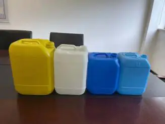
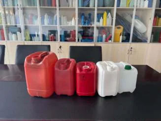
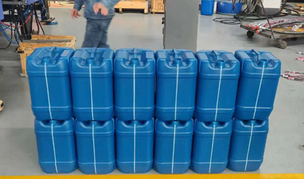
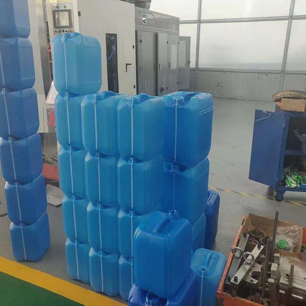
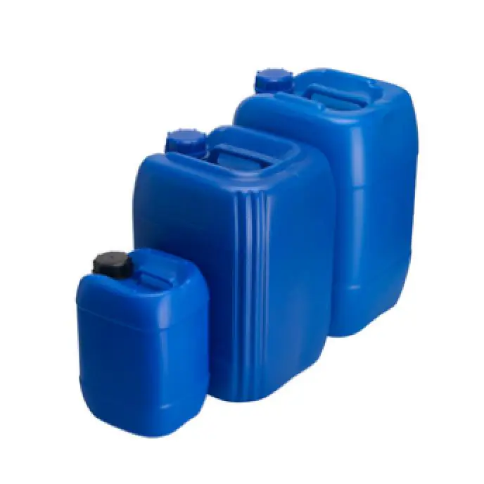
Stackable cans are made by extrusion blow molding HDPE. A parison is extruded, the mold closes around it and compressed air forms the body, handle and stacking features. Continuous-extrusion machines suit small and medium cans; accumulator-head machines are used for larger, heavier cans. Each can is trimmed and checked, including its stacking performance.
| Can size | Machines |
|---|---|
| Up to 12 L | HTII-12L, HTSII-12L, HSII-12L |
| Up to 18 L | HTII-18L |
| 20–30 L | HSII-20L, HWII-30L, HSII-30L |
| 20–50 L (accumulator head) | TDB-50F |
Configurations and specifications: stackable container line configurations · Quotations and project cases: Tongda stacking barrel machines (tongdamachine.net)
Making stackable cans involves the material, extrusion system, mold, blow pin, cooling, trimming and downstream handling. Begin with a drawing or sample and define the nominal volume, dimensions, target weight, neck, handle and intended use. Those details provide a better basis for machine selection than the volume alone.
The application range uses HDPE. Specify the resin grade, color masterbatch and any permitted regrind content against the finished container requirements. A material blend is a project decision: it depends on the container’s contents, appearance, physical requirements and the customer’s specification.
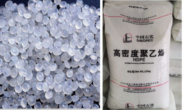
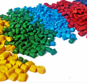
The extrusion system melts the material and forms a hollow parison. The mold closes around the parison, air forms it against the mold cavity, and the part cools before removal. The neck and flash are finished according to the tooling arrangement. The material, parison program, mold and cooling must be tuned together during a production trial.
The stackable-can range uses HT, HTS, HS and TDB machines. Continuous-extrusion and accumulator-head configurations address different product and production requirements. Select the mold envelope and clamping arrangement alongside the volume and weight.
| Model | Stations | Stated maximum volume | Clamping force |
|---|---|---|---|
| HTII-12L | Double | 12 L | 110 kN |
| HTSII-12L | Double | 12 L | 158 kN |
| HSII-12L | Double | 12 L | 158 kN |
| HWII-30L | Double | 30 L | 250 kN |
| HSII-30L | Double | 30 L | 250 kN |
| TDB-50F | Single | 50 L | 260 kN |
Agree output in accepted containers per hour for a named bottle, resin, weight and cavity arrangement. A dry-cycle rate does not include the complete production process. Cooling, extrusion, wall thickness, trimming and downstream handling affect finished-product output. Use an agreed trial to establish the result for the project.
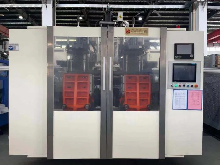
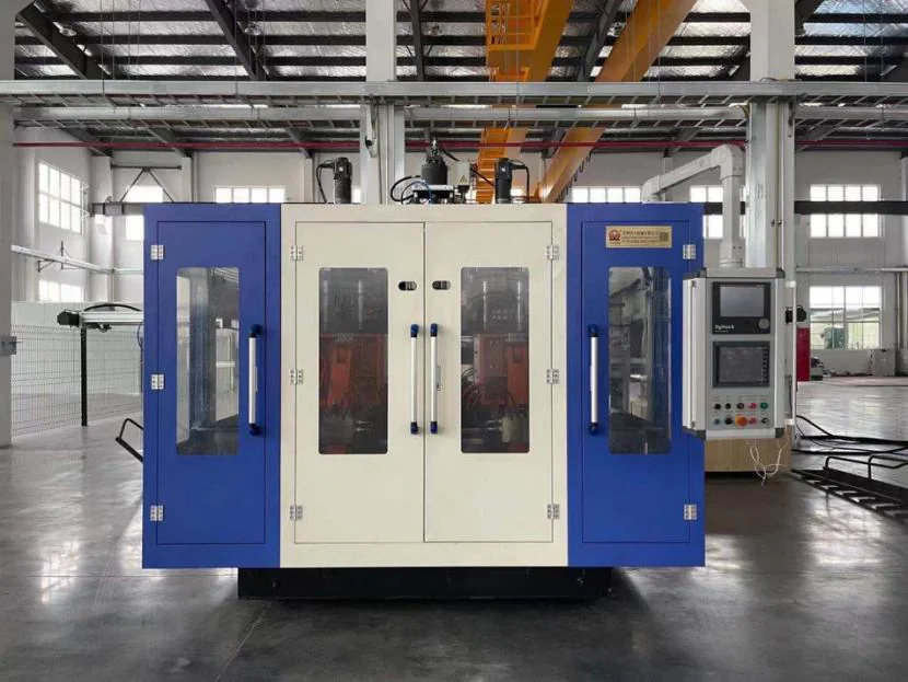
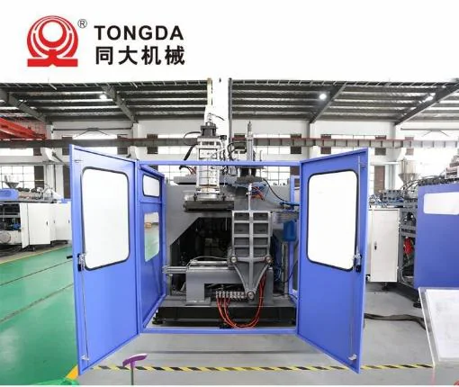
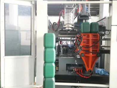
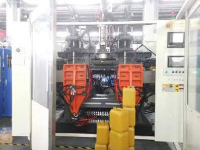
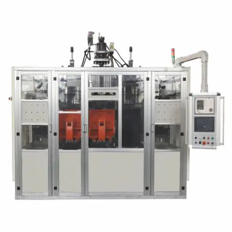
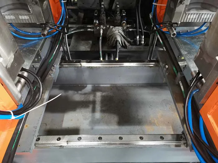
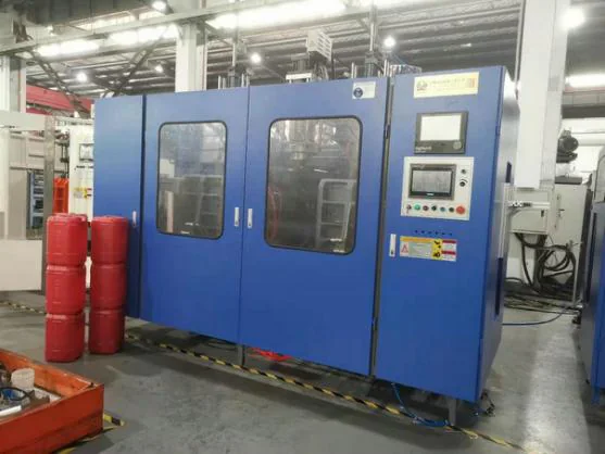
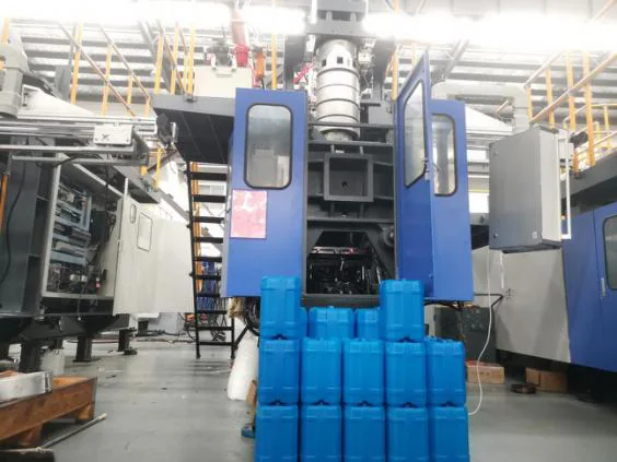
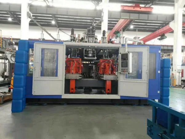
The extrusion-system details identify the gearbox, screw, barrel and driving motor as key components. The screw and barrel affect melting, mixing and delivery of material to the head. Select the configuration for the resin and product requirement; compare the component specification and the supplier’s trial evidence.
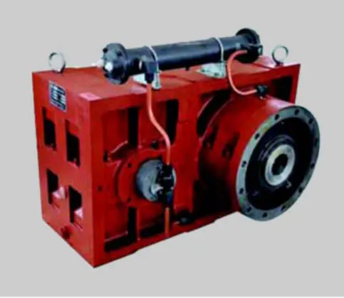
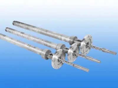
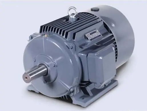
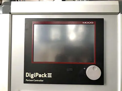
The die head forms the parison from the plasticized material. Its flow path and tooling need to suit the material, product geometry and head arrangement. A parison-control system varies wall distribution along the parison. Evaluate the finished bottle sections, weight and required performance when setting the program during commissioning.
The jerry-can and stackable-can guides describe multi-layer arrangements and a view strip. A view strip helps show the liquid level when the container design and materials permit it. Layer requirements and the use of different materials should be specified for the intended container; they are not interchangeable options for every product.
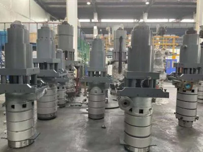
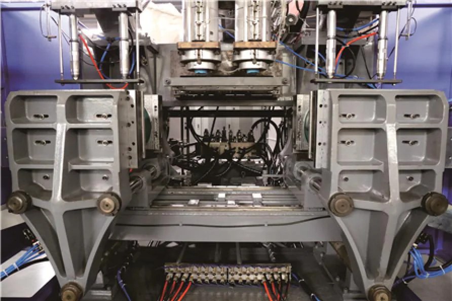
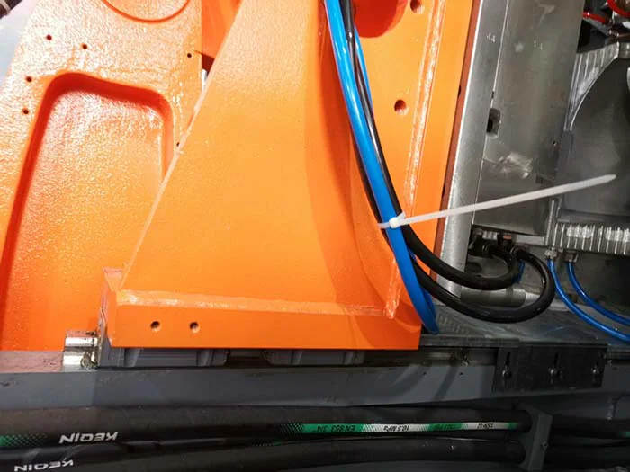
Review the mold’s external dimensions, required opening and mounting arrangement with the machine specification. The machine range shows guided mold movement, toggle clamping and different blow-pin arrangements. Select clamping force and mold support around the actual part and tooling; a larger force alone is not a substitute for a suitable mold design.
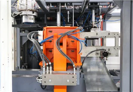
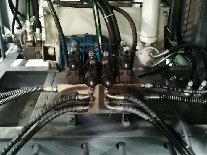
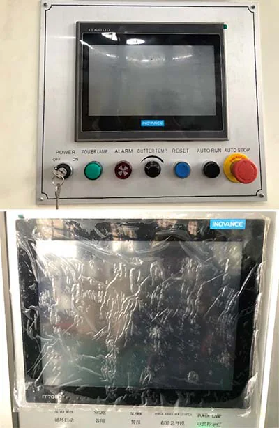
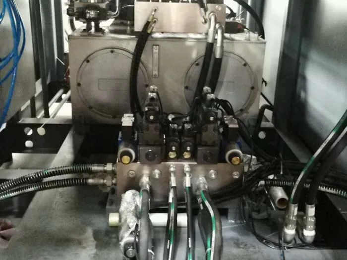
The component illustrations show PLC and touch-screen control, hydraulic valves and parison-control equipment. The interface is used to set, store and monitor operating parameters and display machine faults. Ask for the actual component list and maintenance documentation for the supplied configuration, rather than assuming that every pictured brand is included.
Define how the neck and flash will be finished and how the product will be collected. Automatic deflashing and take-out arrangements can reduce handling steps when they match the mold and container design. Include the conveyor, inspection and downstream interfaces in the project scope.
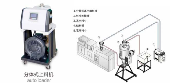
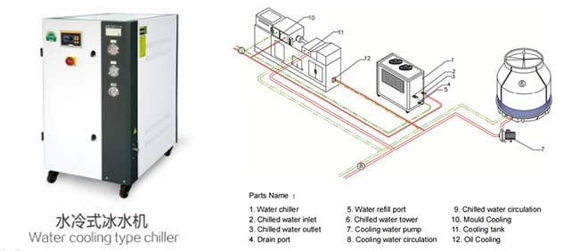
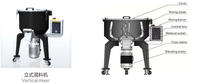
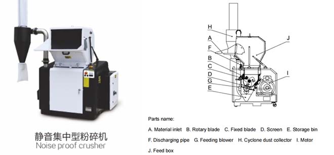
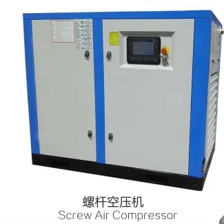
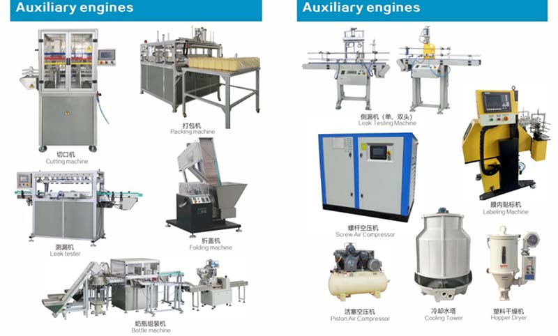
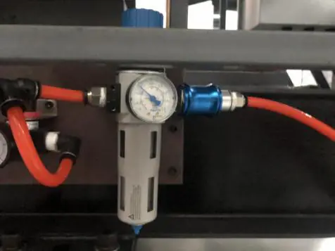
Material loading and mixing, cooling, compressed air and scrap handling all contribute to the production line. The equipment illustrations show autoloaders, mixers, chillers, crushers and air compressors. PC bottle production also includes material drying and mold-temperature control. Size each auxiliary against the actual machine and process requirements.
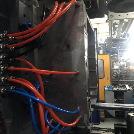
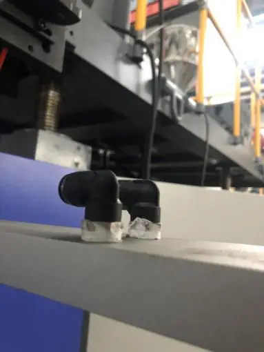
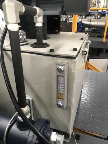
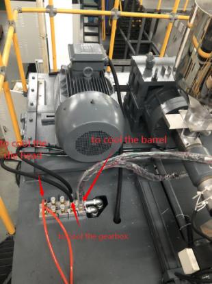
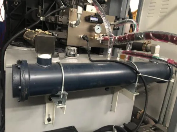
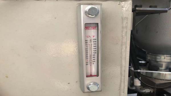
Check the general arrangement drawing, access for installation and maintenance, factory electrical supply, cooling circuit, compressed air and hydraulic requirements. Use the supplied machine documentation for connection and operating values. Installation and adjustments should follow the equipment procedure and be performed by qualified personnel.
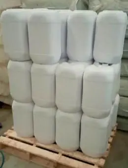
Define the container’s dimensions, weight, closure fit, leak checks and stacking performance with the intended filled load. Handle and base geometry matter as much as nominal volume. Record the trial material and conditions so that the result can be reproduced.
Review the proposed configuration, manufacturing and inspection process, documentation, training, service arrangements and spare parts. Request relevant product videos or a factory discussion, and compare quotations against the same requirements. Include the mold and auxiliaries as well as the machine itself.
Send your drawing or sample, material, volume, target weight, output requirement, head or layer preferences, and factory location. Include any existing tooling and downstream equipment. Continue with the machine selection checklist or the cost planning guide.
Stackable cans in this range are made of HDPE. Specify the resin grade, color masterbatch and any permitted regrind against the contents, the filled weight and the stacking load.
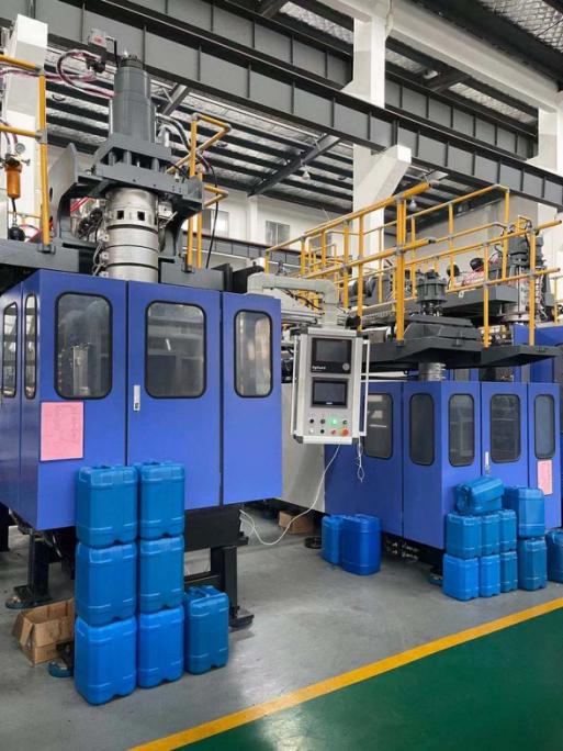
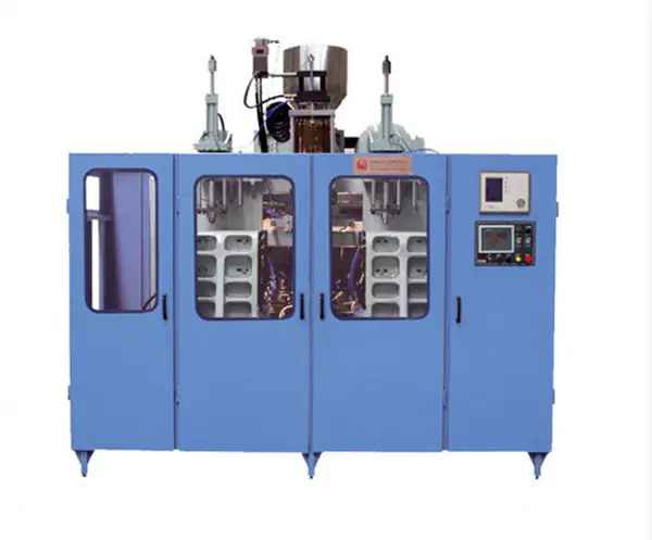
An extrusion blow molding machine. In the Tongda range, HT, HTS and HS machines cover cans up to 30 L, and the TDB-50F accumulator-head machine covers 20–50 L products.
Continuous-extrusion machines suit small and medium cans at higher cycle rates. Accumulator-head machines store melt and push it out quickly, which suits larger and heavier cans. Select the mold envelope and clamping arrangement together with volume and weight.
Define the stacking performance with the intended filled load, together with dimensions, weight, closure fit and leak checks. Handle and base geometry matter as much as nominal volume.
Yes, when the container design and materials permit. Specify the view stripe and any layer structure for the intended contents in the machine and mold specification.
The price depends on the machine type and size, stations and die heads, the mold, deflashing and handling, and auxiliary equipment. Compare quotations against the same container, output and scope; the cost guide lists what to include.
Let's build your next production line
Share your container, material and production requirements. We’ll help you identify a suitable machine configuration.
Discuss your project